SensMonitor integration
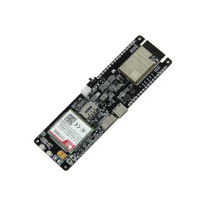
LilyGO T-SIM7080G-S3
Connect an ESP32-S3, SIM7080G Cat-M/NB-IoT modem and BME280 sensor to the SensMonitor platform using the open-source smonitor-iot firmware.
- ESP32-S3Wi-Fi, Bluetooth LE, 16 MB flash
- SIM7080GNB-IoT, LTE-M and GNSS
- BME280Temperature, humidity and pressure
01 / Overview
A modern NB-IoT / LTE-M monitoring node
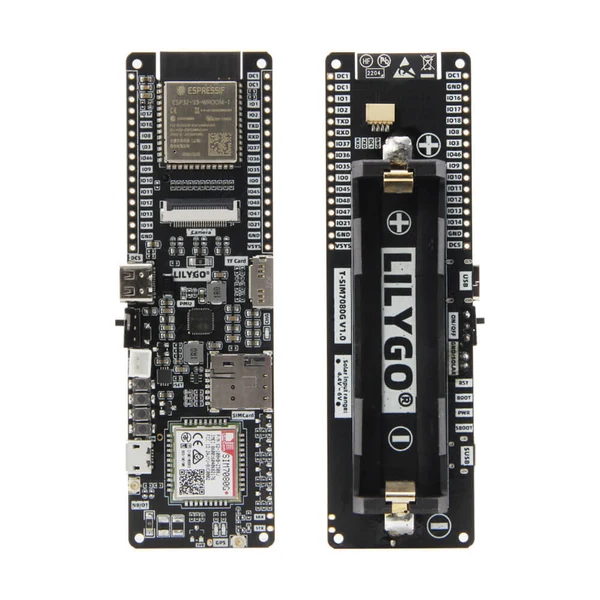
The LilyGO T-SIM7080G-S3 combines an ESP32-S3 microcontroller with a SIM7080G cellular modem. It is a strong candidate for remote monitoring stations where Wi-Fi is not available and low-power cellular connectivity is preferred.
Controller
ESP32-S3-WROOM-1 based board with Wi-Fi, Bluetooth LE, flash and PSRAM.
Cellular network
SIM7080G supports LTE-M and NB-IoT depending on operator coverage and SIM plan.
GNSS location
The SensMonitor profile can read GNSS location before starting the cellular data session.
Sensor telemetry
The initial profile uses a BME280 sensor connected over an external I2C bus.
02 / Preparation
What you need
LilyGO T-SIM7080G-S3 board
Nano SIM card with active LTE-M or NB-IoT data plan
LTE antenna connected before powering the modem
GNSS antenna if location is required
BME280 I2C module and four wires
USB-C data cable connected to ESP-USB
Linux, macOS or Windows computer with Git
ESP-IDF 5.x development environment
03 / Hardware
Connect the BME280
The default SensMonitor profile for this board uses GPIO 13 for SDA, GPIO 21 for SCL and I2C address 0x76. If your module uses 0x77, change the address later in configuration.
| BME280 | LilyGO | Function |
|---|---|---|
VIN / VCC | 3.3V | Power |
GND | GND | Ground |
SDA | GPIO 13 | I2C data |
SCL | GPIO 21 | I2C clock |
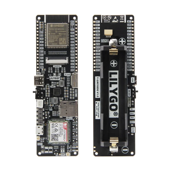
Modem and board pins used by the firmware
These connections are routed on the board and do not need to be wired manually. The PMU bus is used internally for AXP2101 power initialization.
04 / Firmware
Install and configure smonitor-iot
The project targets ESP-IDF 5.x. Internet access is required during the first build so ESP-IDF Component Manager can download SensMonitor components.
- 1
Install ESP-IDF 5.x
Follow the official Espressif instructions, then open a terminal with the ESP-IDF environment activated.
- 2
Download the firmware
git clone https://github.com/sensmonitor/smonitor-iot.git cd smonitor-iot idf.py set-target esp32s3 - 3
Configure the board profile
cp examples/lilygo_sim7080_s3/sdkconfig.defaults sdkconfig.defaults.local
idf.py menuconfig
Open the
SensMonitor IoTmenu and configure APN, PPP authentication, preferred network mode and optional LTE/NB-IoT band settings. - 4
Check the sensor configuration
In
SensMonitor IoT → I2C sensor, keep BME280, SDA 13, SCL 21 and address0x76unless your wiring is different. - 5
Build and flash
idf.py build
idf.py -p /dev/ttyACM0 flash monitor
Replace
/dev/ttyACM0with your board serial port, such as/dev/ttyUSB0on Linux orCOM5on Windows.
05 / SensMonitor
Register the device
The firmware automatically derives a serial number from the factory ESP32-S3 MAC address. The serial number identifies the device and is not a secret.
smonitor_iot: Device serial:
SM-ESP32-A1B2C3D4E5F6

DEVICE_NOT_REGISTERED:
Register SM-ESP32-A1B2C3D4E5F6
in the SensMonitor application.- 1
Sign in at app.sensmonitor.com.
- 2
Open the Devices section and add a new device.
- 3
Select LilyGO T-SIM7080G-S3 as the device type.
- 4
Enter the serial number exactly as shown in the monitor.
- 5
Create a station, assign the device and configure BME280 sensors.
- 6
Restart the board so the firmware can request configuration again.
06 / Verification
What a successful connection looks like
AXP2101 modem power enabledBME280 initialized successfullyGPS location: latitude=...Modem connected to PPP serverWebSocket connectedReceived device-sample-ackReady to measure?
Monitor field data in real time.
Technical sources: SensMonitor firmware, LILYGO product page and LilyGo Modem Series.
Photos belong to their original owner and should be served from the official LILYGO CDN or your uploaded media copy.