
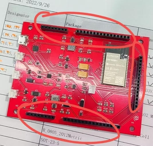
Modular Concept – Expandability
Electronics extendability refers to the ability to expand the functionality and capabilities of electronic systems through the use of modular components. This concept allows for customization, versatility, and scalability, enabling users to adapt their projects to specific needs and requirements.
Electronics extendability also promotes scalability. As projects grow in complexity or additional features are desired, more shields can be added or upgraded. This allows for future expansion and flexibility without needing to redesign the entire system.
The concept of electronics extendability using base boards and shields has revolutionized the field of electronics prototyping and development. It has empowered both beginners and experienced professionals to create custom electronic systems tailored to their specific needs. By leveraging modular components, users can rapidly iterate, test, and refine their designs, enabling innovation and pushing the boundaries of what is possible in the realm of electronics.
Base Board
At the core of electronics extendability lies the concept of a base board. A base board, also known as a mainboard or motherboard, serves as the foundation for building electronic systems. It contains a microcontroller or microprocessor, as well as various input/output (I/O) interfaces and connectors.
The base board acts as a central hub, providing power and communication pathways to the connected components. It serves as a platform for integrating additional modules or peripherals to enhance the functionality of the system. The base board establishes a common interface and standard connections, simplifying the process of adding or removing components.
Shields are typically designed to align with the base board’s connectors, ensuring a seamless and secure connection. This plug-and-play approach eliminates the need for complex wiring or soldering, making it easy for users to extend their electronic systems.
The versatility of shields allows users to customize their projects according to specific requirements. For example, if a project requires 4G(LTE), shield with appropriate cellular modem can be added.
Technical specifications
Dimensions
- baseboard 75*100mm
- box 90*109*42mm
Buttons
There are 2 buttons located on top face:
- 1 power on/off switch
- 1 reset push button
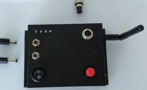
Connectors
There are 5 types of device connectors located on the top face or at the sides of the device:
- 1 SP13 4-poles connectors for the I2C (sensor plug-in inputs) – top face
- 1 JST male/MC4 female connector for the solar panel(s) – top face
- 1 DC power jack female connector for external battery/pack powering – top face
- 1 USB connector (for power supply/charging and data transfer) – left side
- 1-2 SMA female connector for antenna(s) (WiFi, 4G LTE antenna – optional) – right side
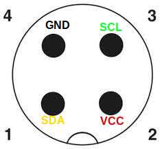
I2C 4-poles SP13 connector pinouts
LED Indicators
There are 4 LED diodes located on top face of the device which defines current state of the device and visually indicate active process and possible errors in work. Any active LED indicator means device is switched on. With separate jumper/switch it is possible to disable all LED indicators (silent mode). Particular functionality for each LED indicator:
- Charging status (on/off)
- Standby status (on/off)
- WiFi status (on/off, short blink 10ms for sending data using WiFi)
- Cellular 4G (LTE) status (on/off, short blink 10ms for sending data using lte)
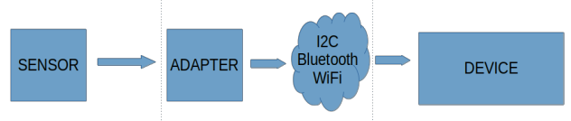
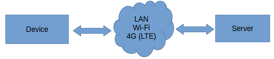
Communication
Full-duplex communication protocol over single TCP connection provides bi-directional full-duplex communication channels over a single TCP connection interface. That allows not only using sensors as analog inputs, but also using analog/digital inputs and outputs. There are 2 communication types:
- Sensor – Device (simplex)
- Device – Server (full-duplex)
Network
Device-sensor (beside direct I2C plugin) communication supports 2 network communication channels:
- WiFi
- Bluetooth
Device-server communication supports 3 TCP network communication channels:
- WiFi
- 4G mobile (LTE) – optional (shield)
- Ethernet (LAN) – optional (shield)
Wi-Fi
- Standard :FCC/CE-RED/IC/TELEC/KCC/SRRC/NCC
- Protocol :802.11 b/g/n(802.11n,speed up to1 50Mbps) A-MPDU and A-MSDU polymerization,support 0.4μS Protection interval
- Frequency :range 2.4GHz~2.5GHz(2400M~2483.5M)
- Transmit Power :22dBm
- Communication distance : 300m
Bluetooth
- Protocol meet Bluetooth : v4.2BR/EDR and BLE standard
- Radio Frequency : with -97dBm sensitivity NZIF receiver Class-1, Class-2 & Class-3 emitter AFH
- Audio Frequency : CVSD&SBC audio frequency
Powering
Working voltage is 3.3v. Input voltage range is 3.2v(LiFePO4) – 3.7v(Li-Ion 18650, Li-Po). The external power supply can be independently designed according to the desired capacity and plugged into DC power jack.
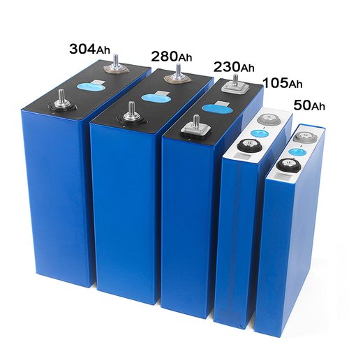
LiFePo4 Batteries
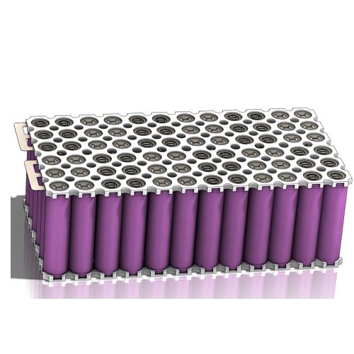
Li-Ion 18650 Battery Pack
External MPPT controller can be used by connecting it’s DC output to DC power jack of the device. Device working current is up to 250mA (full working mode with active network communication and GPS).
Charging
USB
MicroUSB, allows stable voltage powering and charging battery at the same time. Charging current is about 780mA.
Solar Panel(s)
Solar input voltage range: 4.4-6V.
Antenna(s)
| Location | Connector | Case | Frequency | Gain | |
| WiFi | external | SMA male | plastic | 2.4GHz | 12dBi |
| 4G (LTE) | external | SMA male | plastic | 2.4GHz | 18dBi |
| GPS | internal | SMA IPX | ceramic | 1575MHz | 24dBi |
Memory
Internal memory:
- Flash – 4MB
- EEPROM (part of flash) – 1KB
- RAM – 4MB
- PSRAM (pseudo static RAM) – 8MB
External memory:
- MicroSD card memory – up to 1GB
MicroSD Card (optional)
Using MicroSD memory card is optional, and also optional use by software settings. In case MicroSD card is recognized, and device settings checked (turned on), it will be used as sending data cache for data loss prevent purpose7. This mechanism stores every data sending to the server to the memory card before sending, waiting on confirmation (ACK) that data sent are properly received on server side. Once receiving ACK for the certain request, data will be removed from the memory card. On this way ensures secure data transfer to the server in case of server unavailability (e.g. temporary losing network connection, poor signal, …). Storing data contains also timestamp information, so once server connection available, information of time when data was made will be valid.
Firmware
Stored in flash memory. Thanks to the use of special abstraction layer in code on top of the TCP/IP stack, firmware code chooses between IP stacks. Other words, firmware uses same and unique code independently and regardless on available network type: Ethernet, WiFi, cellular mobile network, … This allows great code consistency for all network media types, without separate coding parts specific for different particular networks.
Update
Supports remote online firmware update. On every restart (which also can be remotely), device checks active and latest available version, in case are different – update starts with LED diode indication.
Features
Multiple Devices
SensMonitor supports multiple devices/sensors monitoring and analytics. At any moment you can see if the device is active or not and as well as all of the sensor values for each station, analyzed by a period (last hour / day / week /month / year / custom).
Choose and Adjust Sensors
New feature which separate SensMonitor from other monitoring systems is possibility of choosing and adjusting custom sensors. You can define, project and add new station with standard sensors (temperature, humidity, pressure) or you can add custom sensors which are more suitable for you.
Support and Maintenance
We stand behind our products and provide a declared period warranty. In case of failure we will fix the device, or replace it with the new one.